|
|
||||||||||||||||||||||||||||||
| Date | Event | |||||||||||||||||||||||||||||
|
01/10/2006
3hrs Battery |
The paint is dry. at last and I refitted the brackets and the battery. I started to fit the battery leads, I made yesterday, when I came across a potential problem. I considered there was a safety problem when fitting the battery leads that it may be possible to touch the retaining bracket and the battery post. The resulting short circuit, though brief would at minimum cause a spark and at worst a fire. In situ it was fine but in the heat of the moment to change a battery there was the potential to have an accident. It's funny how your first idea is the correct one and subsequent attempts at refining or altering the design don't work. so it was with the battery retaining bracket. Originally I had planned to use a standard angled battery clamp on to the front of the battery and had changed my mind to a vertical clamp for improved security. luckily Al the alterations I had made to the restraining rods still allowed me to go back to the original design. Clamping the battery at the front edge removed the possible hazard, so this is what I ended up doing. The battery is securely fixed and the clamps on the battery posts are free from interference. | |||||||||||||||||||||||||||||
|
03/10/2006
1hr Battery Wiring Tests |
Just an hour today to start testing the wiring. I connected the
battery positive lead but NOT the negative. I removed the permanent on
fuses BF6 - BH8. It is worth noting that as fitted to my car and listed in
the build manual the fuses are numbered Right to left i.e. fuse 8 is
extreme left and fuse 1 is extreme right. I made sure all the
switches were off including the ignition switch. I connected a test
lamp between the negative lead of e battery and the battery. Not
surprisingly the lamp illuminated, indicating there was a wiring problem
or possible short circuit somewhere in the system. I removed the
remaining fuses in order, one at a time, testing with the test lamp after
each fuse was removed until the lamp failed to illuminate. BF2 (7.5A)
LH dip beam appeared to be the offending circuit. I replaced all the
fuses except BF2 and the lamp remained extinguished. I removed al the fuses
again and replaced BF2 the lamp was once again illuminated. Leaving the fuse
in place I disconnected the Leads from the LH headlamp, at the snap
connectors joining it to the main loom. one at a time and testing with
the test lamp after each one. Disconnecting blue/red lead from the
headlamp the lamp extinguished. This looks to be the culprit. By
the time I found this, it was getting dark and I need to garage door
open to remove the headlamp and examine the wiring. I did one final
test with a multimeter between the Blue/red lead and the battery earth
and there appears to be a short circuit in the headlamp. I will investigate
and fix tomorrow. |
|||||||||||||||||||||||||||||
|
04/10/2006
7hrs Headlamp Wiring |
I rechecked the headlamp wiring, the problem was still there. I
compared left with right and could see no difference in the wiring and
inside the headlamps was identical. I removed the instrument
panel so that I could get easy access to the lighting relay. Once
again the wiring seemed to be in order, connection wise, except that there
was a discrepancy between the loom and the build manual. I had noticed
this before but dismissed it as a modification incorporated during
development of the loom. I was tracing the wiring circuit with a
multimeter and couldn't get a reading between the fuse box and the dipped
beam connection on the relay. According to the build manual there
should have been a Blue/Red (O/S dipped beam) and Blue/Pink (N/S dipped
Beam) to fuses BF3 & BF2 respectively. This cross checks with
the XJ6 wiring diagram. In my loom there was no blue/pink wire neither
at the lighting relay or at the fuse box. In fact fuse BF2 was
connected to a brown lead which usually indicates a permanent battery feed.
If this was true this would explain the fault I had experienced. I
undid some of he cable ties securing the loom and removed the fuse box. the
existing Blue/ Red wire wasn't ot making good contact with fuse BF3 I
re-seated it and this restored the connection to the relay. However BF2 was
definitely connected to a the permanent supply and not to the relay.
The output of the fuse boxes to the headlamp assemblies looked OK I
called Nostalgia but they could not explain the reason for the brown lead.
They are going to send me a wiring schematic to help sort it out. I
decided the loom was incorrectly made. I disconnected the brown lead
from the fuse box and made a new Blue / Red lead (couldn't find any
blue/pink wire) between the fuse box and the relay. This wire
was joined to terminal 56b with the existing blue / red wire. I
taped the new wire back along side the loom and refitted the fuse box. I
refitted the headlights. I put all the fuses back except BF6 to BF8 and
repeated the original test with test bulb between battery negative lead and
negative terminal. This time the bulb did not light. I inserted
the remaining fuses and connected the battery negative lead. No
drama's followed. I started testing the circuits that operate with the
ignition switch off. The Hazard warning flasher does not but not at
work, the horn does, the side lights work at the back, with the number plate
illumination. but not at the front. I started investigating the front
side lights not working. Neither the sidle light built in to the
headlamp not the side light on top of the wing on either side of the car
work. I soon found the problem. there are 3 black (earth) and
3 coloured leads (Red/Black - N/S and Red / White - O/S) to
connect the side lights. I quickly determined that the pairs of wires
that I had used for connecting both side lights were
interconnected but had no supply voltage on them and the spare leads
had +12 and earth. The loom is obviously configured for connecting one
of the side lights and not both. I need to work out how I can connect
both side lights to the supply.
|
|||||||||||||||||||||||||||||
|
05/10/2006
1hr Side light wiring |
I fixed the front side lights not working today. It involved making a small
adapter comprising 2 x 2" pieces of wire joined together and soldered
or crimped to a Japanese snap connector to form 2 tails. the other
ends of the wires were soldered or crimped to Japanese bullet connectors.
The adapter was installed by connecting one of the bullet connectors
to the side light live connection in the wiring loom ( RED / Black -
if you are working on the N/S, Red / White - if you are working on the O/S
). The Japanese snap connector is connected to the Red sidelight wire
in the headlamp. The final bullet connector is connected to the snap
connector at one end of the side light link wire. The other end is then
connected to the side light on top of the wing.
|
|||||||||||||||||||||||||||||
|
06/10/2006
1hr Main Beam Warning lamp |
I thought that the main beam warning lamp was not working. I disconnected the
battery and removed the dash panel. I checked the connections to the lighting
and the instrument plug #2. All seemed OK. I reconnected instrument plug #2
and the battery and the warning lamp worked. It may have been a poor
connection in the instrument plug or may be I couldn't see the lamp was
working in daylight. Whichever it works now.
The rest of the time I spent troubleshooting the hazard warning flasher
so far without success. |
|||||||||||||||||||||||||||||
|
07/10/2006
5hrs Indicators & Hazard Warning |
The wiring diagram I was expecting from Nostalgia arrived this morning.
I had already started troubleshooting the indicators using the XJ6
wiring diagram . The new diagram arrived showing that the classic 120 was
wired differently but it gave some important clues. I discovered
that the flasher output should be connected to the Hazard warning
switch and the indicator switch which was not the case in my wiring loom.
The warning lights weren't shown in the nostalgia diagram and the
hazard warning lamp was shown connected to the C terminal. Tracing the
wiring loom and using a combination of both wiring diagrams I cam to the
conclusion the wiring loom was incorrectly made certainly incorrectly
connected. I considered that the problem was exaggerated by the
alteration I had made to the loom to not use the indicator lights in the
instruments and to get all the warning lights in front of the
driver. On re-examining what I had done I dismissed this and I am
firmly convinced the loom is at fault and would never have worked. The
possible causes , change to the loom and the build manual and the two not
being synchronized or just plain bad workmanship. I was even
more convinced when I discovered that the Feed from the hazard warning
switch to the flasher looked to be undersize to carry the current of all the
indicator lamps at once. Admittedly it is pulsed and ot continuous current
but it was half the size of the wires connected to it from the steering
column and those provided in the loom for the warning lamps. |
|||||||||||||||||||||||||||||
|
08/10/2006
6hrs Indicators & Hazard Warning |
I thought long and hard yesterday on how I could correct the wiring
situation without a major rewire of the loom. Since the loom provided two
wires from the flasher unit to the warning lights I could use them. I
would still mean a certain amount of rewiring but no massive
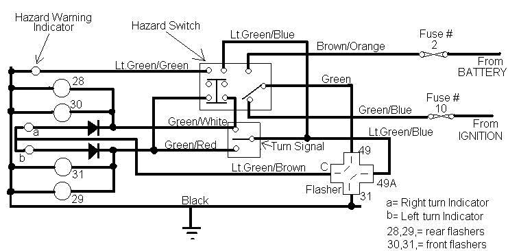
disturbing of the loom. I decided to copy the XJ6 circuit as below
I started by rewiring the indicator warning lights by including the two blocking diodes. I had some miniature diodes (IN4006) that I could incorporate in to the leads. This is only needed if you don't want the indicator warning lights to flash when the hazard switch is operated. In operation the indicator warning lamps will flash in the direction of the turn. In hazard mode the turn warning lamps will be switched off and the hazard warning lamp will flash. Secondly I removed one of the Green / Brown wires provided in the loom as a feed from the flasher unit to each warning lamp. I connected the lamps together and fed them to a single lead. The other end of this lead already went ot the flasher via instrument plug #5 and there I connected it to the "C" terminal. I checked the Hazard warning lamp that it was connected to the LTV Green / Green wire in the indicator stalk loom. I disconnected the remaining Green / Brown wire in Instrument plug #5. The other end of this lead is connected to the Flasher unit " 49a " terminal. I found the thin Lt Green/ Blue lead in the steering column indicator loom and disconnected it from the Mate-N-Lock plug cut it off and tied the remainder back into the loom with insulation tape. I made a new Green / Blue wire crimped an male blade terminal on the end and inserted in to the Mate-N-Lock. I ran the new Green / Blue wire around the loom to the vicinity of instrument plug #5. For the most part this wire was incorporated in to the loom with loom tape and insulation tape but where it was exposed i was covered with PVC tube and taped to the side of the loom. I joined the new Green / Blue wire to the Green / Brown wire I had removed from instrument plug # 5. This made the connection from terminal 49a on the flasher unit to the indicator switch and the hazard switch. I tidied up all the wiring to make it safe and reconnected the battery. Testing the Hazard warning system, the indicators now flash but the warning lamp doesn't Further investigation is required. Testing the turn signals the indicators work but the warning lamps are reversed, this will be a simple matter of swapping over the two leads on the back of the panel.
|
|||||||||||||||||||||||||||||
|
09/10/2006
1hr Indicators & Hazard Warning
|
The problem of the indicator warning lights being crossed over was easily
fixed by swapping the wires on the back of the warning light panel.
While I had got this dismantled I checked out all the wring to the
hazard warning light. It all checked OK, which pretty much pointed to
the switch. The contacts of the switch are difficult to get to while
in situ. At this point the Haynes manual for the XJ6 comes to the rescue.
I dismantled the upper steering column following the procedure in the
book and removed the column switch assembly. With the switch on the
bench I could confirm the switch was faulty. Closer examination showed
one of the spring plungers on the operating lever, that keeps the pressure
on the contacts, was missing. Applying manual pressure to the contacts
restored the connection but at the next operation of the switch it failed.
I decided to contact SNG Barratt for a replacement. Since it was pretty late
in the day I placed the order over the Internet in the hope of getting the
new one by Wednesday, |
|||||||||||||||||||||||||||||
| 11/10/2006
4hrs. Hazard Warning Switch |
The new hazard warning switch and a replica XK120 bonnet badge arrived at
lunch time. I had carefully noted the connections on the back of the old
switch before removing them and the switch. I fitted the new switch
making sure I connected the leads to the correct terminals. Testing
the the switch before refitting the assembly to the car ,I discovered that
the switch diagram in the HM had the pins incorrectly numbered. For a
start it refers to pin 9 and there is no pin 9 on the switch.
The correct connections are:-
The colours of the wires may vary according to the date of manufacture Testing the old switch now that it was removed confirmed there was no connection between pin one and pin 4 when the switch was operated. I refitted the switch assembly and steering wheel, the reverse of the dismantling procedure. Just a couple of things to watch make sure the slots in the collar line up with the key in the steering wheel adjuster and the horn connector in the steering column slides in to the hole in the centre of the steering wheel adjuster. I rechecked the steering wheel cancelled the indicators when operated and was central when the wheels were straight. (This will be need to be checked again when the steering geometry is set up.) I refitted the warning panel and the instrument panel. I reconnected the battery and set about testing al the lighting and warning functions again. The Hazard Warring now functions correctly as do the turn indicators. Side lights headlights, dipped and main beam all function as before. fog light and corresponding warning lamp function correctly. Low Brake fluid and Hand Brake warnings all work . The reversing light did not work and a thorough check of the wiring revealed no +12v feed to the gearbox switch. This meant the removal of he fuse boxes to locate a bad connection on fuse IF3. once the fuse box was out it was obvious that the lead was not correctly plugged into the base of the fuse box. This was soon rectified. and the lamp worked. The low oil pressure warning light does not work but there is no oil in the engine which may be the reason. I does work if the lead is disconnected from the switch and connected to earth. Indicating the switch may be faulty. The windscreen wipers work as does the heater fan. I finished the day recharging the battery. While the battery was on charge I fitted the new XK120 replica badge to the bonnet. |
|||||||||||||||||||||||||||||
|
14/10/2006
5hrs Starter Motor |
I can't remember when I fitted the starter motor but it seems a long time
ago. I remember thinking to fit it before I fitted the inlet manifold
because it would be a pig to get at afterwards. Well the chickens have come
home to roost! When I was testing the wiring last week. I
accidentally switch the ignition switch to start mode. There was a brief
noise from the starter motor but only brief before I switched off. Last
Friday I decided to check the starter would turn the engine. Switched on -
nothing happened. The starter relay clicks but the starter does not
actually turn. This despite it working in the XJ6 and having tested it
before I fitted it to the engine. Saturday I spent rechecking the
electrical wiring and testing the starter relay. All seemed to be well so
there was nothing for it but to remove the starter. Working from above
and past the back of the inlet manifold is indeed difficult, but
eventually I found the way. Disconnect the battery. disconnect
the Battery supply lead to the Starter motor at the bulkhead. this is fairly
easy to reach from behind the inlet manifold. Next disconnect the starter
solenoid feed from the starter relay. disconnect the solenoid earth
from the earthling point on the water rail. It is easier to do this and
remove the wiring with the starter motor than try to disconnect it at the
starter motor. From within the wheel arch disconnect and remove the oil
pressure sender. Located immediately to the rear of the starter motor.
The starter motor is threaded and held in place by two bolts from the
gearbox side of the engine. The top one is very difficult to get at from
above, the manifold, wiring and heater pipes get in the way but not
impossible. the lower one can be reached from within the wheel arch if the
closing panels are not fitted. The easiest way I found is
working from underneath the car the bolts can be reached with a 9/16 AF
socket. Once the bolts are removed the starter motor can be slid back
towards the front of the car and lowered downwards to remove it.
I removed the battery from the car and used a set of jumper leads to help
test the starter. The solenoid took current but did not move. I separated
the solenoid from the starter motor and tested it again. This time it moved.
It also made the connection across the supply terminals to the starter
motor. I examined the starter motor itself. The pinion drive
moved went the solenoid lever was operated but may7be it was stuck and I
feed it when I disturbed it. More to the point there was no continuity
through the armature. I fitted the solenoid back and tested it
again this time the pinion dive moved but it was intermittent, sometimes it
would stick and need to be helped to operate. I had seen enough
I will order a new one on Monday. |
|||||||||||||||||||||||||||||
|
15/10/2006
4hrs Bonnet Safety Catch |
Since we have got to wait for a starter motor, today seemed like a good
opportunity to fix the bonnet safety catch which had worked loose.
I removed the oil cooler because it was in the way of reaching the
bolt securing the catch to the front cross member. I attempted
to tighten up the bolt only to discover that I had gotten over exuberant and
stripped the thread where the bolt was secured to the mounting bracket. I
took the compete catch and mounting bracket off and dismantled it I
removed the mounting bolt. Fortunately it was the bolt that was stripped and
not the tread in the mounting bracket, I fitted a new bolt, this time
with a shake proof washer behind the head for improved grip and
thread lock. When the thread lock was dry (about 45mins later)
I reassembled the safety catch and bracket. During the refitting of
the I found that the bonnet lock mechanism got in the way of adjusting the
catch and tightening up the bolt. So I removed the bonnet lock .
Finally I was able to secure the catch to the cross member securing it
with a M5 plain washer and nyloc nut. I refitted the bonnet lock and
adjusted the release cable. I refitted the oil cooler . Whilst writing
this it has occurred to me to make a small modification to the catch
end stop. currently this is flat plate riveted to the cross member to hold
the catch in a more upright position to make sure it engages in the bonnet
slam plate automatically when the bonnet is closed. I'm going t make a
small alteration to it so that as well as acting as an end stop it
prevent sideways movement by extending a small tongue inside the safety
catch,
|
|||||||||||||||||||||||||||||
|
18/10/2006
5hrs Starter Motor |
By the time I finish this car I'm going to be an expert at changing starter
motors. the new starter motor arrived yesterday and today was the
first chance I had to fit it. I connected all the wiring to he starter
motor but first I had to make a new connection to the solenoid wiring.
I took the opportunity to shorten this wire by about 2". I
tested the starter motor using jump leads and the Car Battery. All seemed to
work fine as soon as the solenoid lead was touched to the battery +ve
terminal. The trick to fitting the starter motor is to feed it up from
underneath the car between the chassis rail and the engine taking care not
to foul the fuel pipes. Then slide then slide the starter motor forward.
Make sure you have fitted the spigot plate ot he starter motor and it is the
correct way round. The dowels / spigots fit in to the holes in the bell
housing. I didn't have this problem since someone ha cut the dowels off of
my plate. Offer the starter motor up to the bell housing align it with he
holes and insert the bottom bolt finger tight (enough to start the thread
and align the starter motor). Insert the top bolt. This is awkward to
get at but can be started by hand reaching in from the wheel arch. It
may be necessary to get help or use a block of wood to support the starter
motor. From underneath the car and behind the bell housing tighten the
bolts using a socket , extension bar and ratchet handle.
Reconnect the wiring (black) to earth point on the water rail, (red)
battery positive to the bulkhead connector, (White / Red to the start relay.
Before I tested it the car I changed the oil pressure switch for a new one.
One point of note is the oil pressure switch is fitted to the engine block
with and adapter. It is easier to remove the adapter and the switch as a
unit and then transfer the new adapter to the switch and refit.
I reconnected the battery to the car. The oil pressure warning light now
works . Switching the ignition key to the start position the starter
now operates but does not turn the engine. The starter is
reliable and operates every time but it is as though it is spinning
free air. I was expecting it not to mesh or partially mesh with the
starter ring, because the bell housing and flywheel are of unknown
origin and the Getrag box form and XJS, but not this. I had noticed
when I unpacked the starter that stamped on the body was 2M100 but I
dismissed it. It looked physically like the one I had taken off , it fitted
but ... Nothing for it but to take it off again. I tested if off
the car, it still worked but the pinion wheel ,perhaps, did not go far
enough forward as it should. Just my impression since the old one wasn't
working and I didn't have one to make a comparison. The body was
stamped 2?100. I'm pretty sure the ? is an M but in any case it begins with a
2 and I need a 3M100 the same as I removed. I sent an e-mail to Barratt's
overnight and await a reply. I contacted Nostalgia to find out
what modifications, if any, are made to get the starter motor ot engage if
it does not fit initially. |
|||||||||||||||||||||||||||||
|
19/10/2006
1hr Starter Motor |
Barratt's contacted me this morning and are going to send another starter.
This time definitely a 3M100. Nostalgia have at admitted that they
normally have the bell housing modified to overcome the problem but they
have no record of what type of bell housing or flywheel they supplied.
We will wait and see if the new starter motor fixes the problem. If not it
looks like the gearbox and bell housing will need to be removed for
modification. We will see what tomorrow brings and the new starter
motor arrives. With hind sight I would advise anyone undertaking the manual gearbox conversion to fit he bell housing, without the gearbox connected, To the back of the engine. Fit he starter motor and observe through the back of the bell housing if the starter motor is engaged. That's the theory it may not be that easy in practice. |
|||||||||||||||||||||||||||||
|
21/10/2006 5hrs Starter Motor |
|
|||||||||||||||||||||||||||||
|
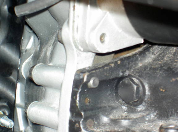
The size of the of the problem is illustrated above. The Gearbox. Bell
housing & flywheel were supplied by Nostalgia but there is no record
of where they come from. The gearbox is presumed to be ex XJS but there is
no clue to the flywheel and Bell housing. Fitting the standard XJ6
starter motor leaves a 13mm (½") gap underneath the starter
motor when located in the holes in the bell housing. It then becomes clear
that mounted like this the starter motor is too high to engage in the
flywheel. I've decided rather than struggle to get the gearbox and
bell housing out in my garage there will be time and it will be easier to do
it when the car is at Nostalgia being finished I've started the finishing
jobs to get the car ready to going to Taunton. I've cleaned the brake disks
and fitted the bonnet safety catch stop. |
||||||||||||||||||||||||||||||
|
29/10/2006
8hrs Accelerator cable |
Progress continues to be made but slowly. I've fitted the accelerator
cable. Nothing much to say apart from it the cable exits the cockpit above
the pedal in to the RH wing void. I found it was necessary to open up the
hole in the top of the bulkhead slightly, to get the cable to fit. I sealed
the cable in place with sealer. It is then a matter of choosing a route with
gentle bends to avoid stiffness and ensure the cable operates smoothly to
attach it to the throttle body. I followed that by finishing the
wiring of the throttle switch and the vacuum full load switch. This
job tuned out to be much longer than anticipated. I first had to identify the
connections in the fuel injection loom and then extend the wiring to reach
the switches. The connections in the fuel injection loom were pretty tatty
so I chose to make new ones. This is what took the time because the
there was only limited space t work in between the pedal box, and clutch
master cylinder. It took several attempts before I was satisfied with the
quality of the connections. I've sorted out the vacuum piping for the
distributor and full throttle switch by using a "Tee" piece and the tubing
from the XJ6. The original XJ6 vacuum installation contained a one way valve
and additional tubing to control the heater system. All this can be
discarded leaving a long tube from the distributor to the "Tee" piece. A
short tube from the "Tee" piece to the manifold ( Located at the rear
and underneath the manifold), The final arm of the "Tee" Piece
connects via a length of tube to the full load vacuum switch. Last Job
of the weekend was to locate all the components for the air flow meter and
start sorting out how the brackets need to be modified and fitted to the
inner wing return. |
|||||||||||||||||||||||||||||
|
Total Hours this Month = 57 hrs |
Total hours to date =1965.0hrs | |||||||||||||||||||||||||||||
 |
 |
|||||||||||||||||||||||||||||